Introduction
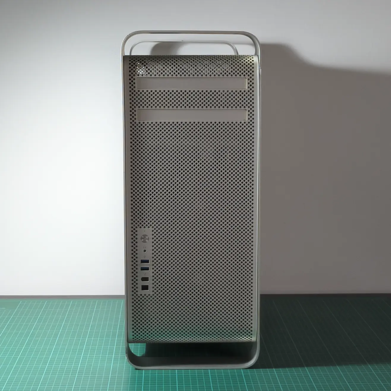
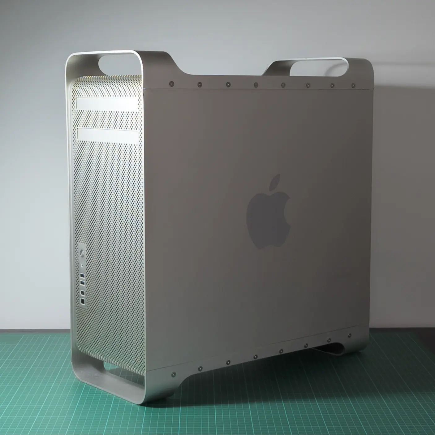
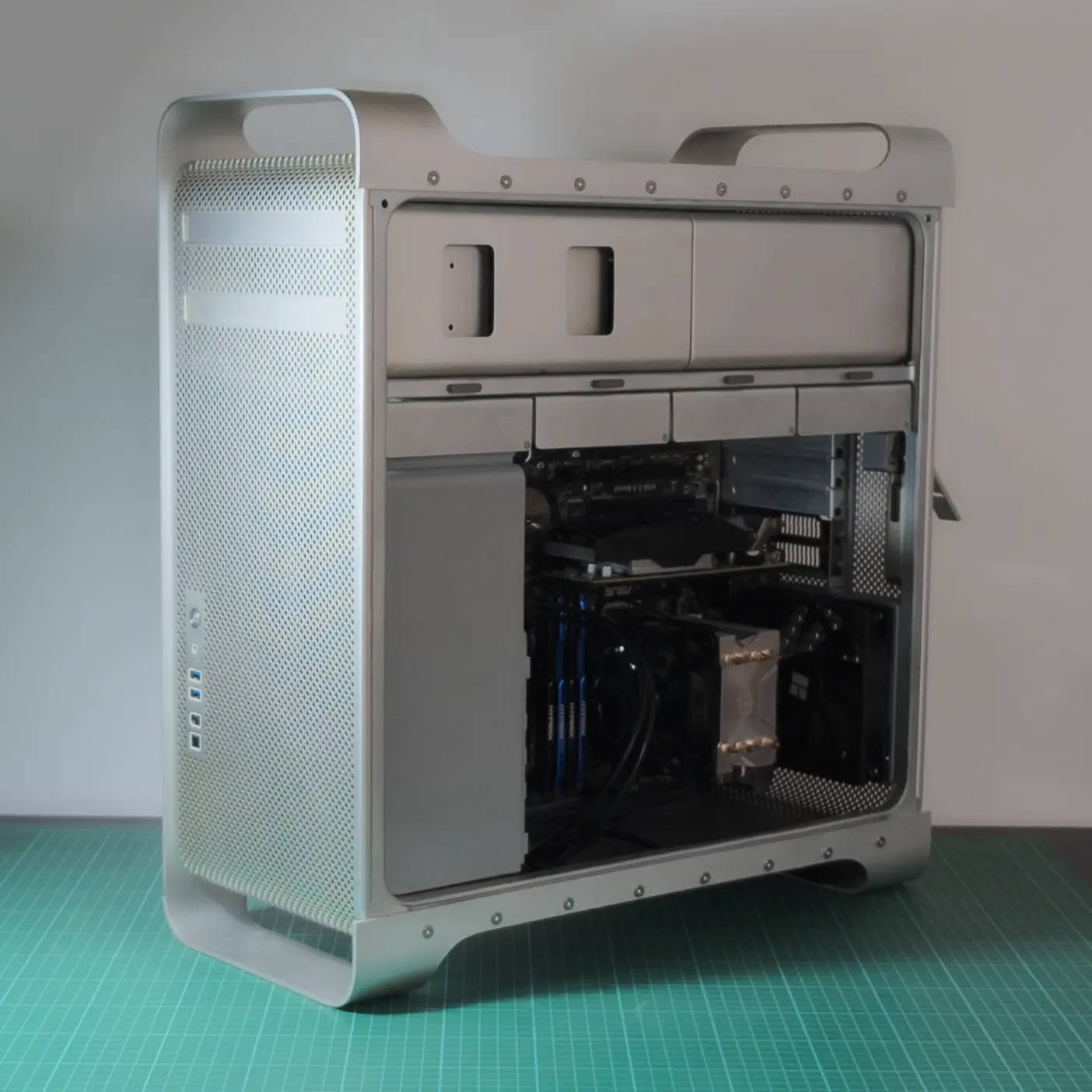
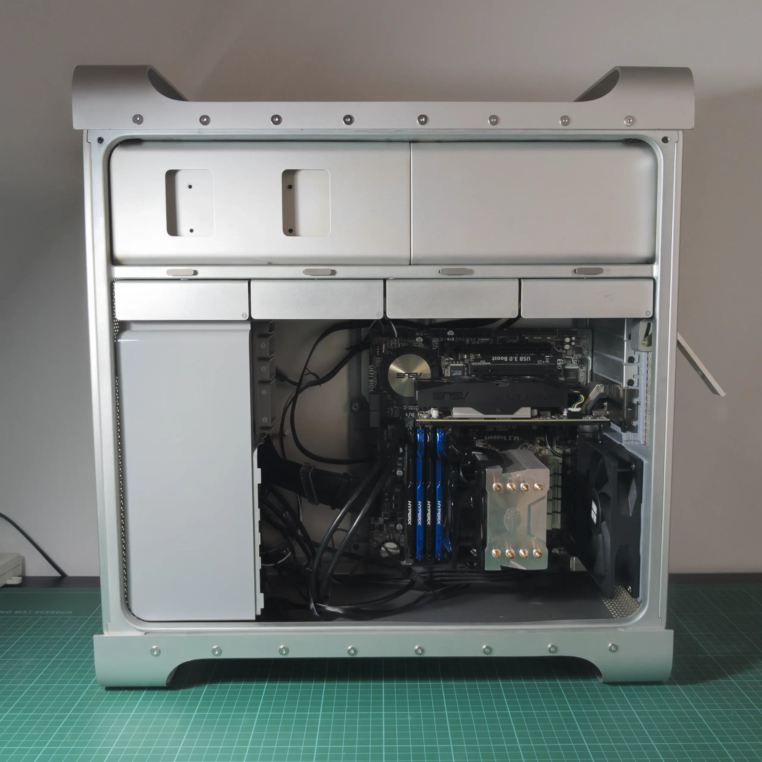
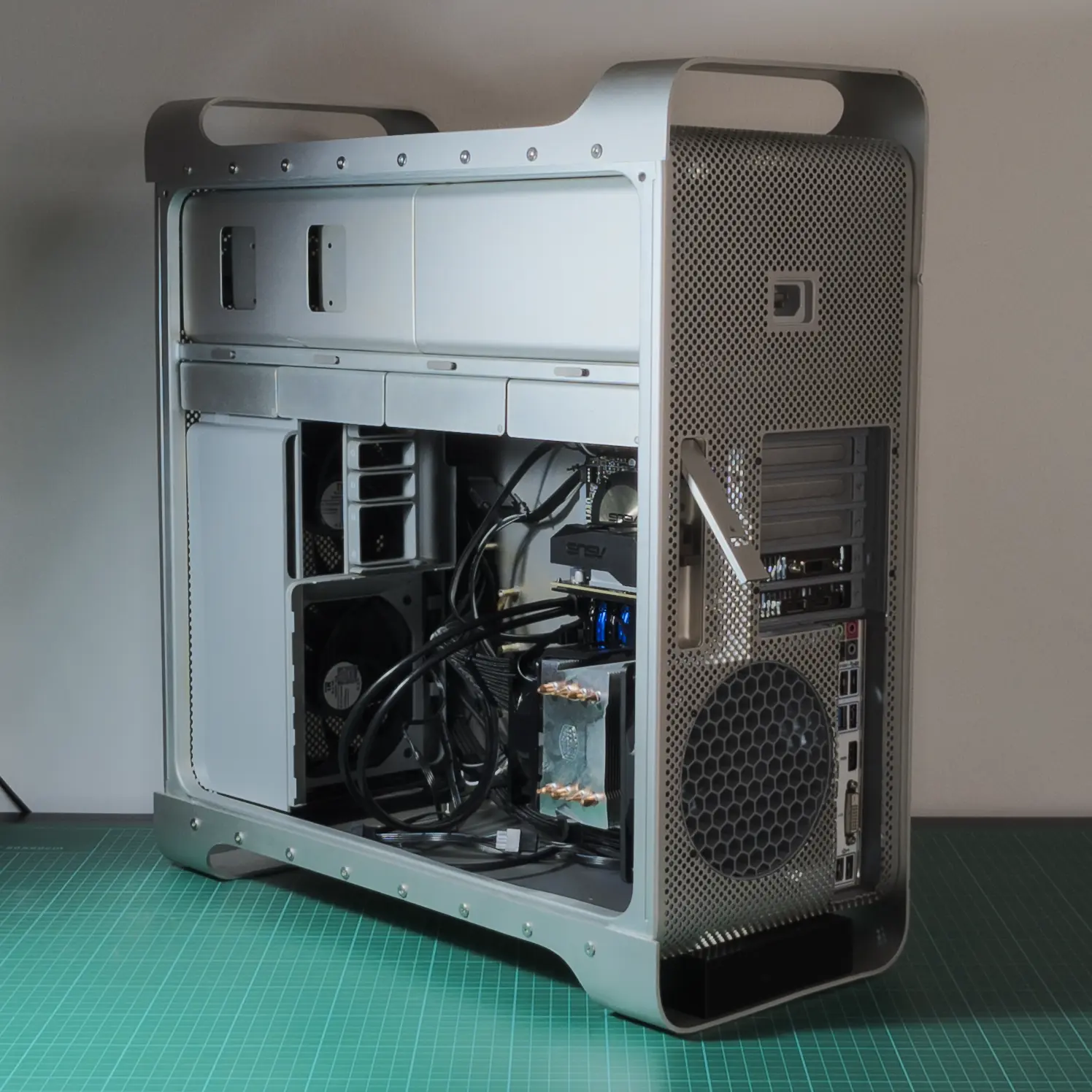
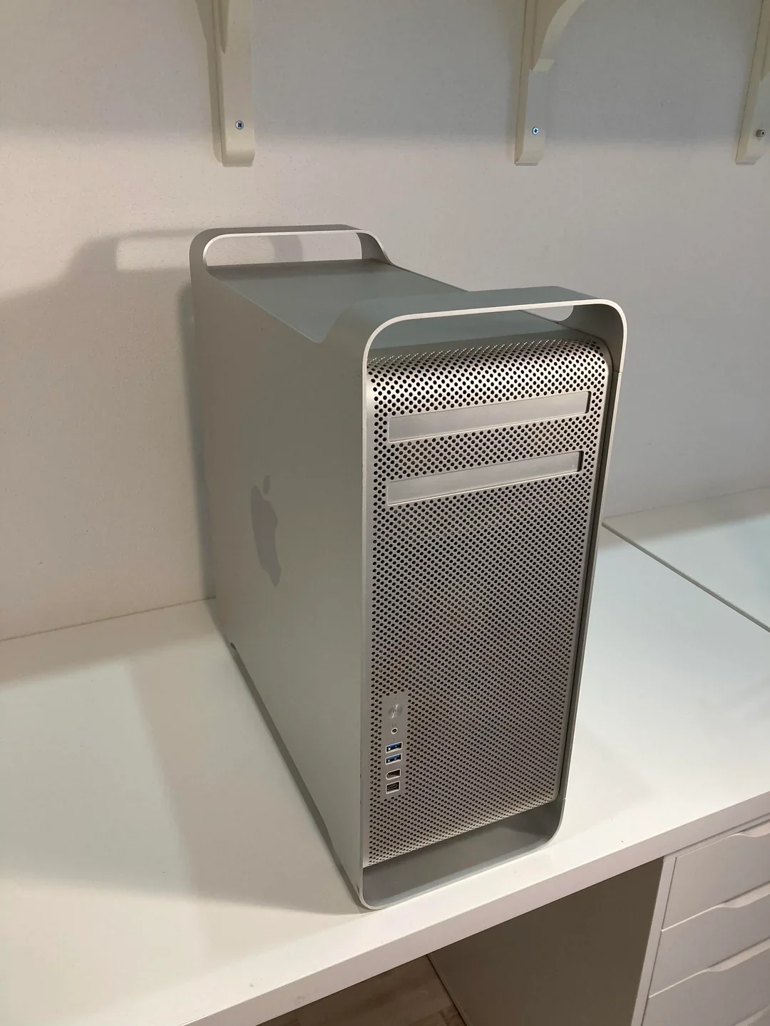
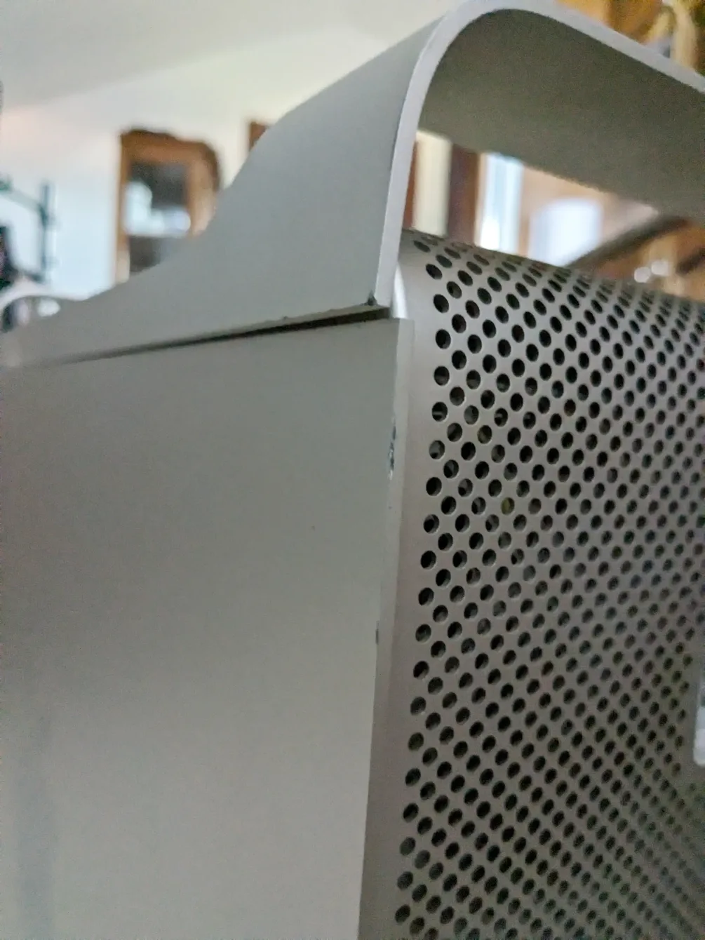
“Sleeper PC” from an old – broken – Mac Pro 1.1 case (2006) that I restored and converted to fit standard PC components. It fits an M-ATX motherboard, an SFX power supply, GPU or PCIe card up to 4 slots, 4x 3.5″ HDD (or 8x 2.5″ SSD).
Table of contents
00 | Research
00 | Research |
Inspiration
Similar projects I used as inspiration and to find relevant information.
neilhart on tonymacx86.com
neilhart’s Mac Pro Hack
Similar project with a lot of resources for wiring and disassembly.
RaoulX86 on reddit
2006-8 Mac Pro ATX Conversion Guide
More recent project with a lot of resources and detailed instructions.
00 | Research |
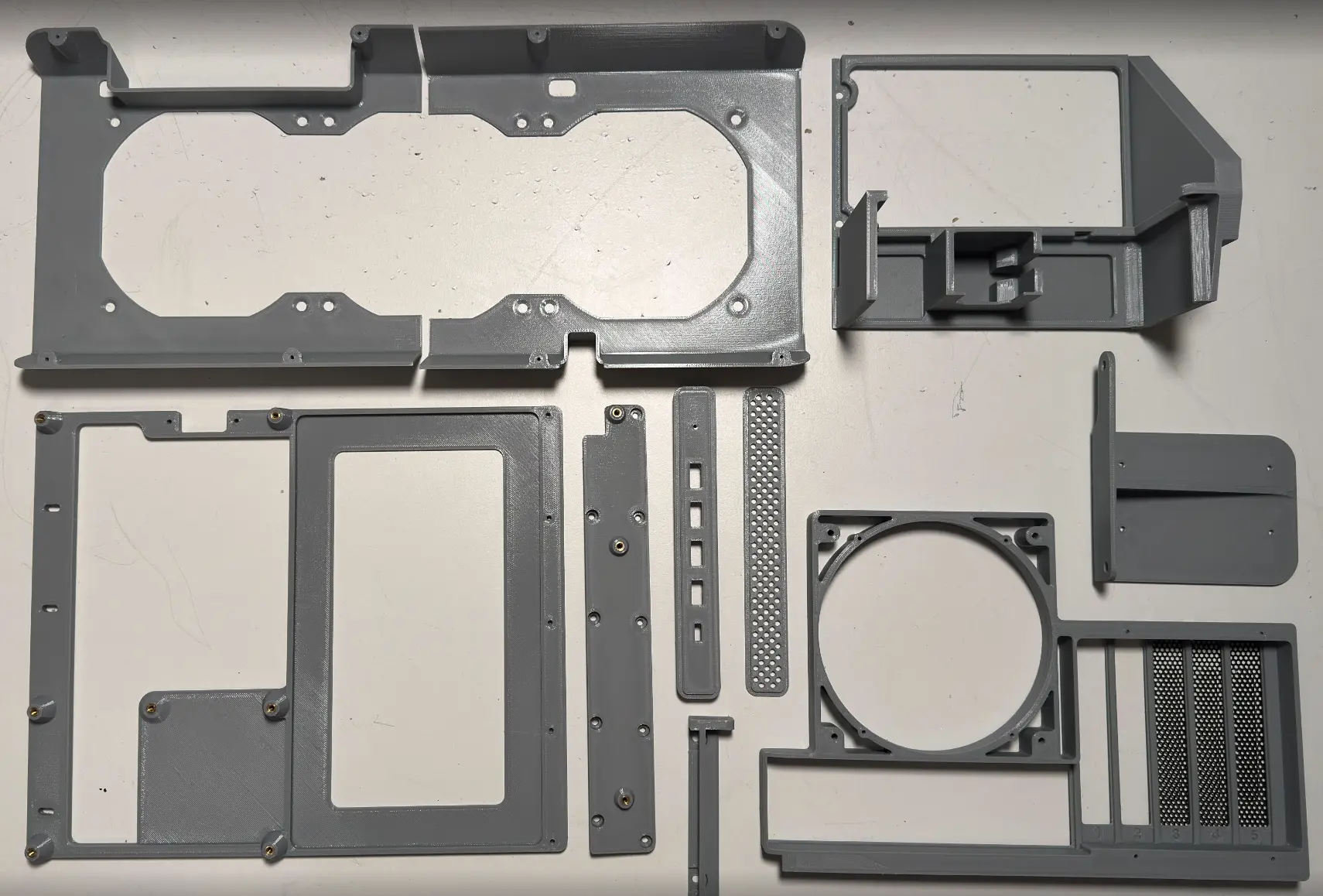
3D printed parts
3D printed models I used in a the project.
stefbond on cults3d.com
MacPro 3.1, 4.1-5.1 ATX Conversion Full Package
Package I used for the motherboard tray (slightly modified to keep the PSU tunnel) and the back IO.
me on printables
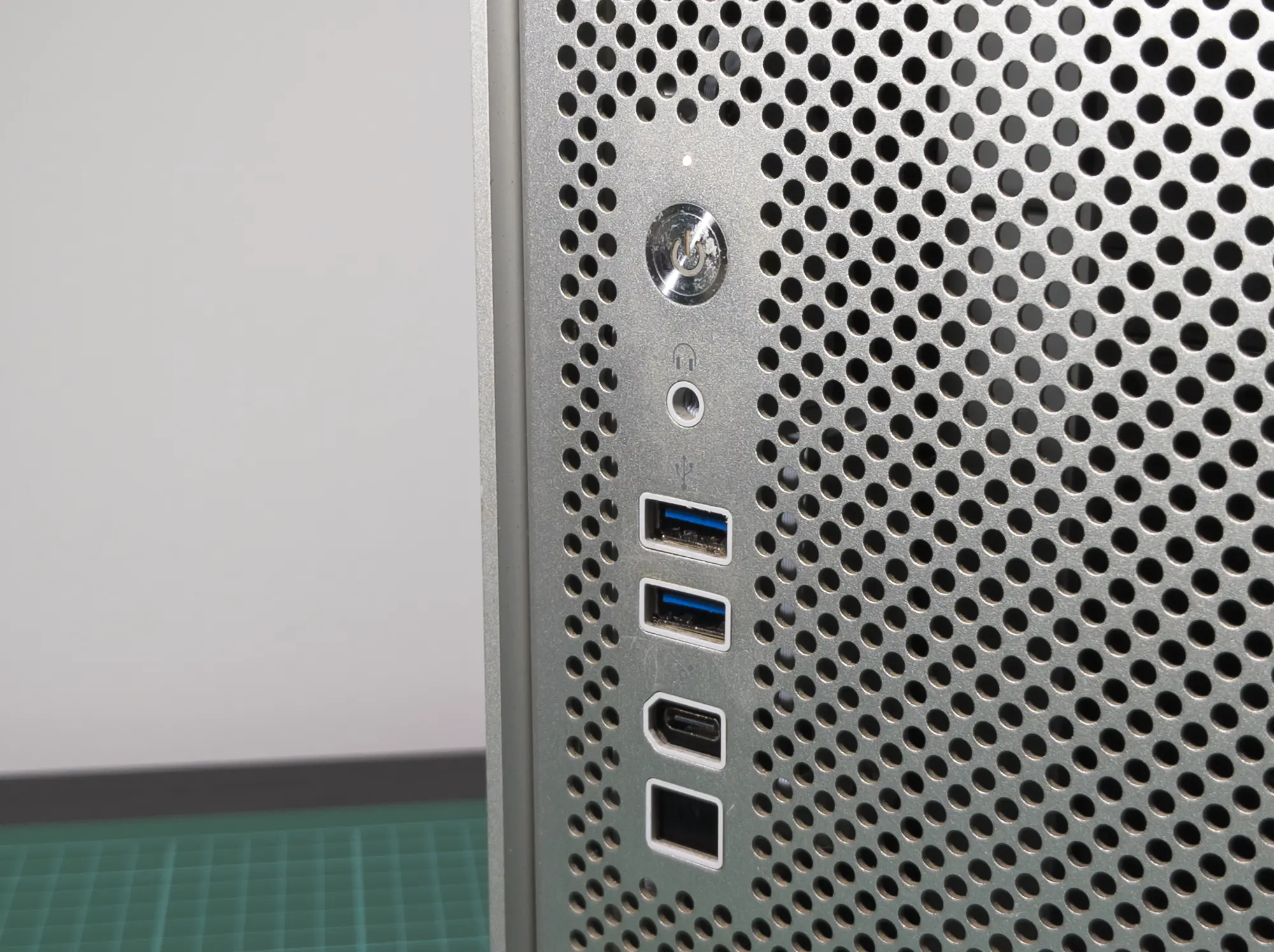
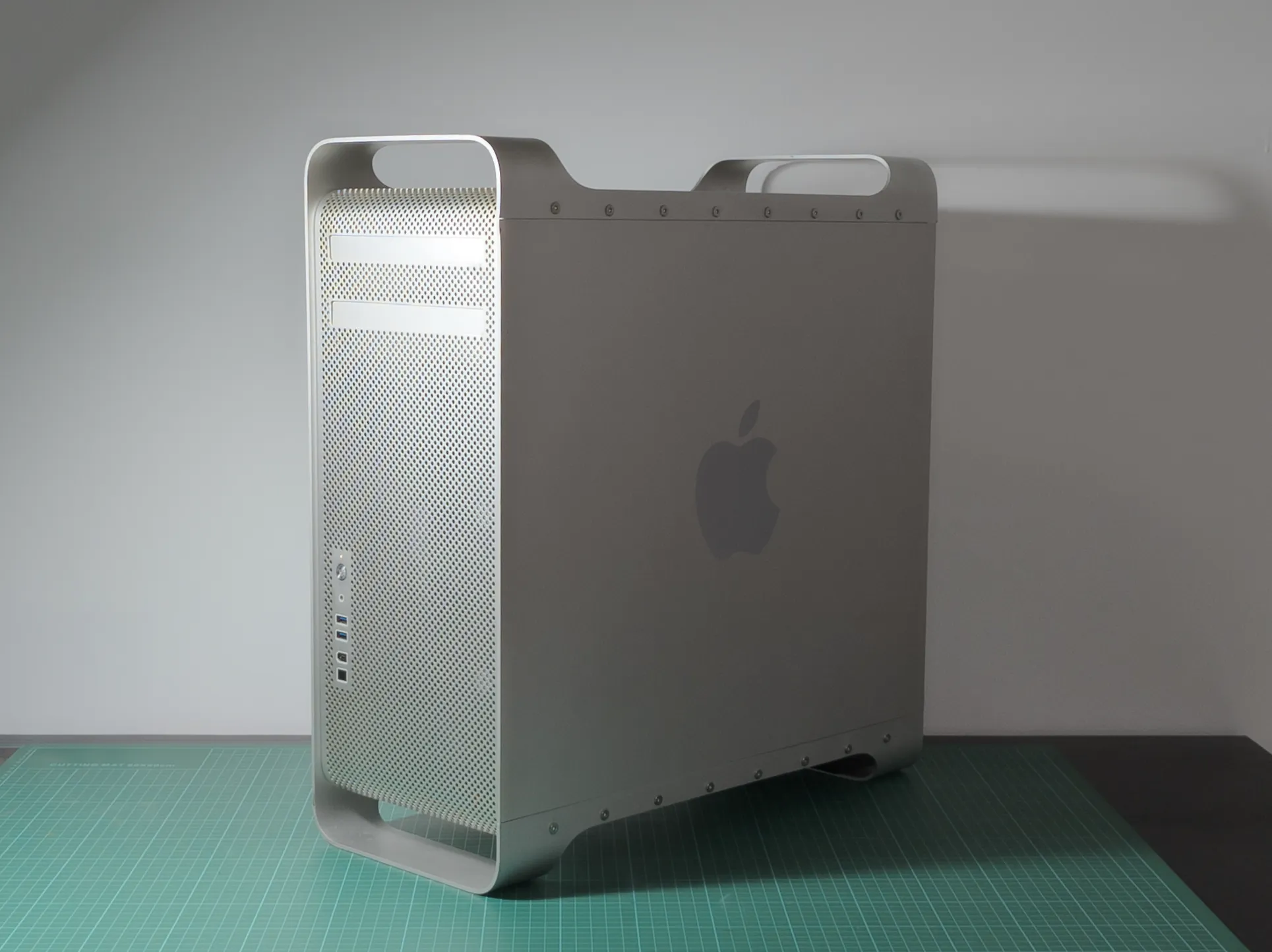
USBa and USBc Front IO panel for Mac Pro 1.1
Bracket I designed for the Front IO panel
01-02 | Design & Prototype
01-02 | Design & Prototype |
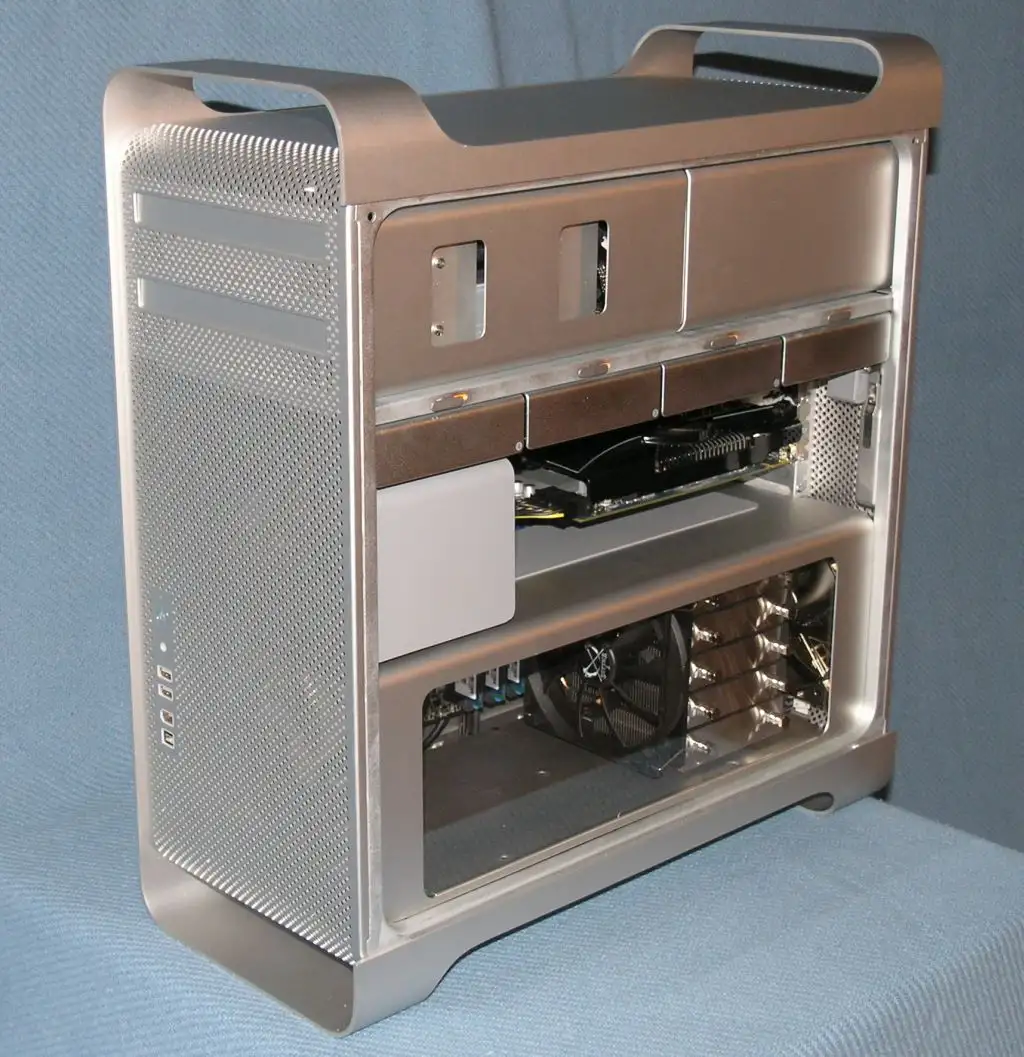
M-ATX conversion
For the M-ATX conversion I used the resources above, slightly modified to fit my use-case. I suggest using the original resources as a guide.
01-02 | Design & Prototype |
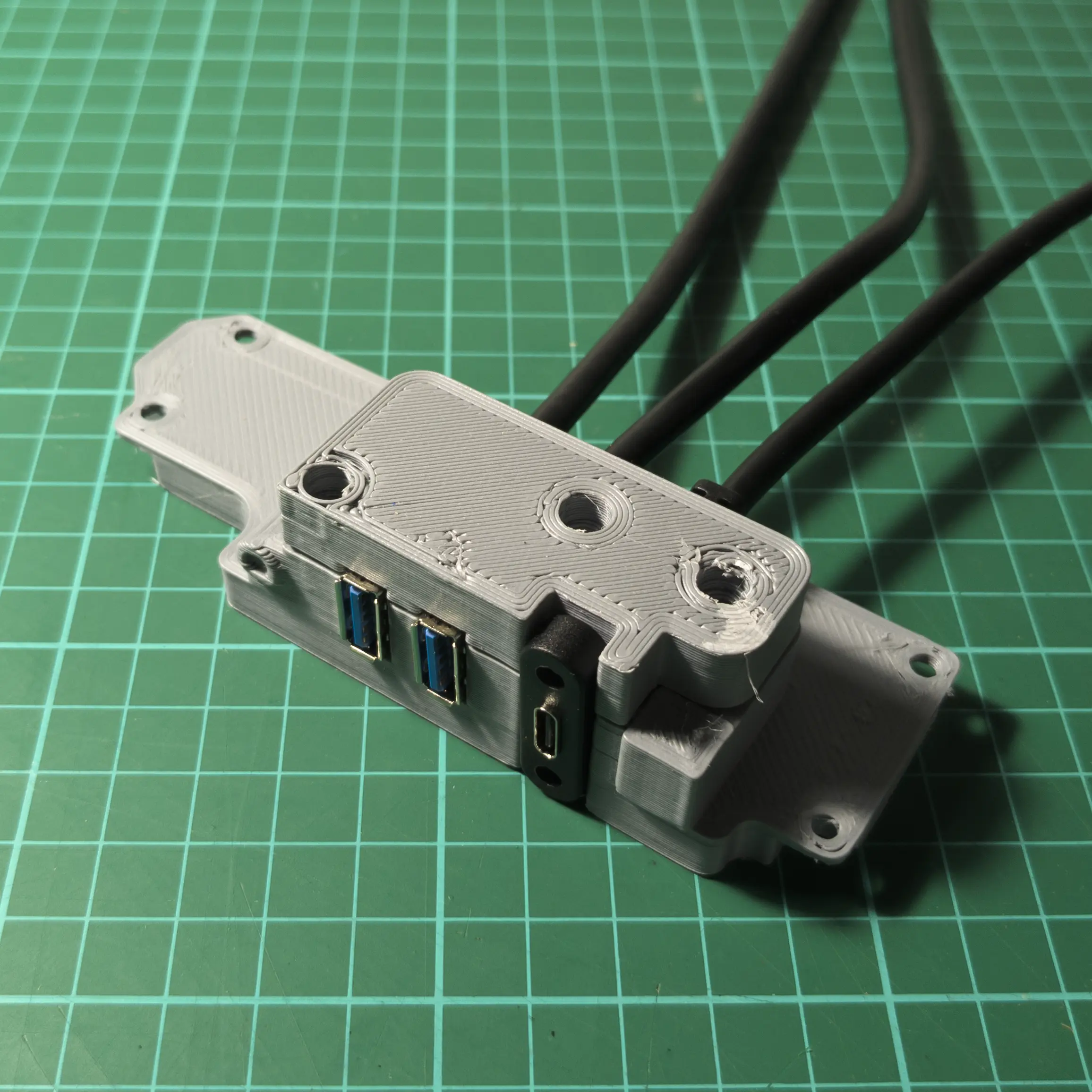
Front IO bracket
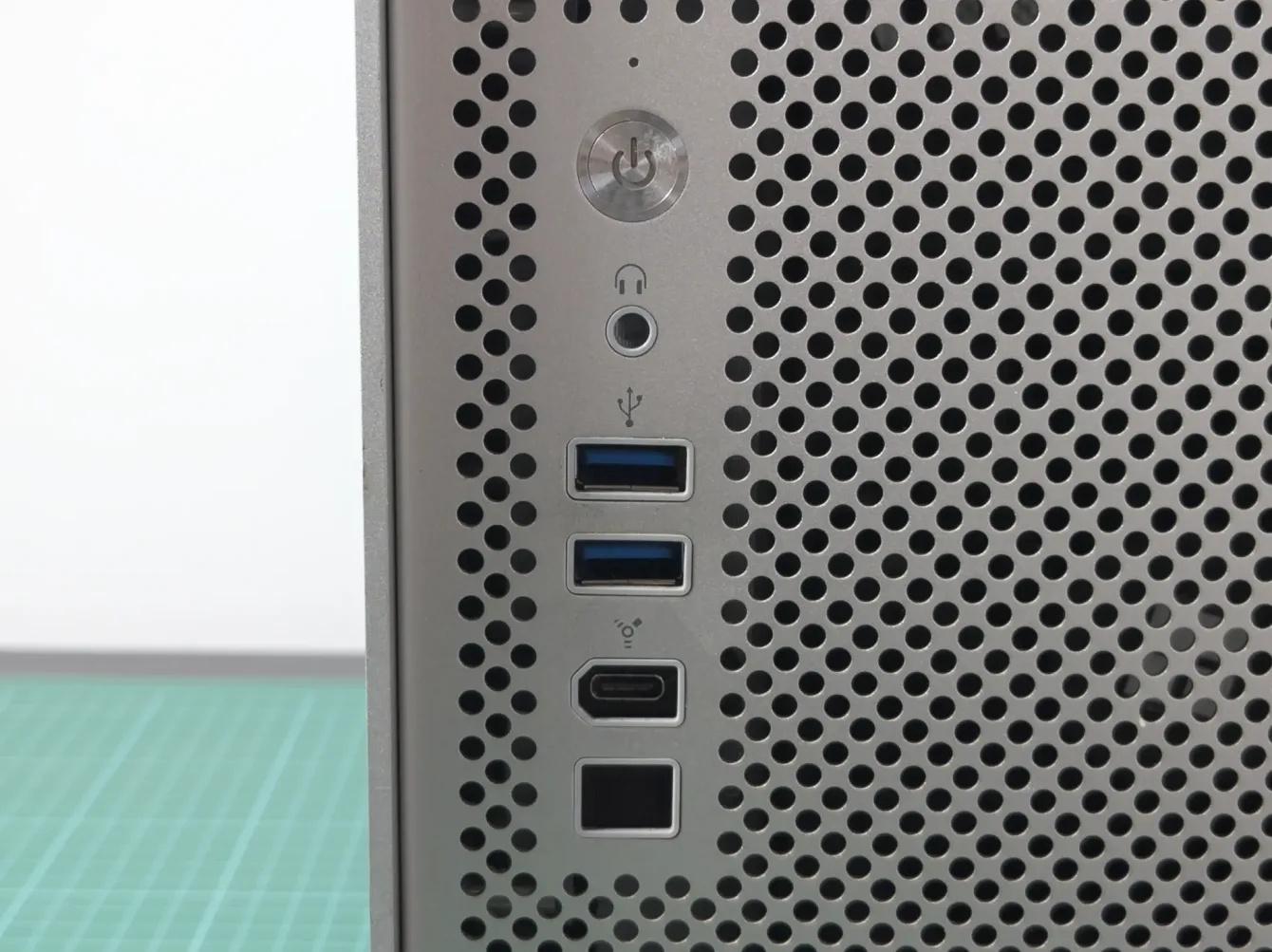
The files (free download) and a detailed description on how I made the front IO bracket to fit the USB-a and USB-c cables are available on printables:
03 | Make
03 | Make |
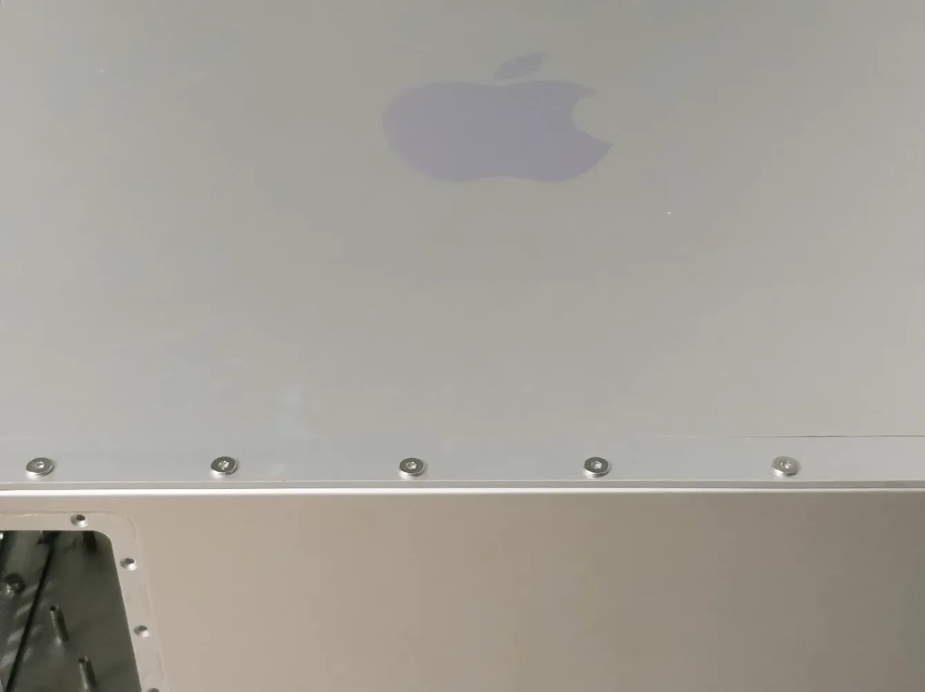
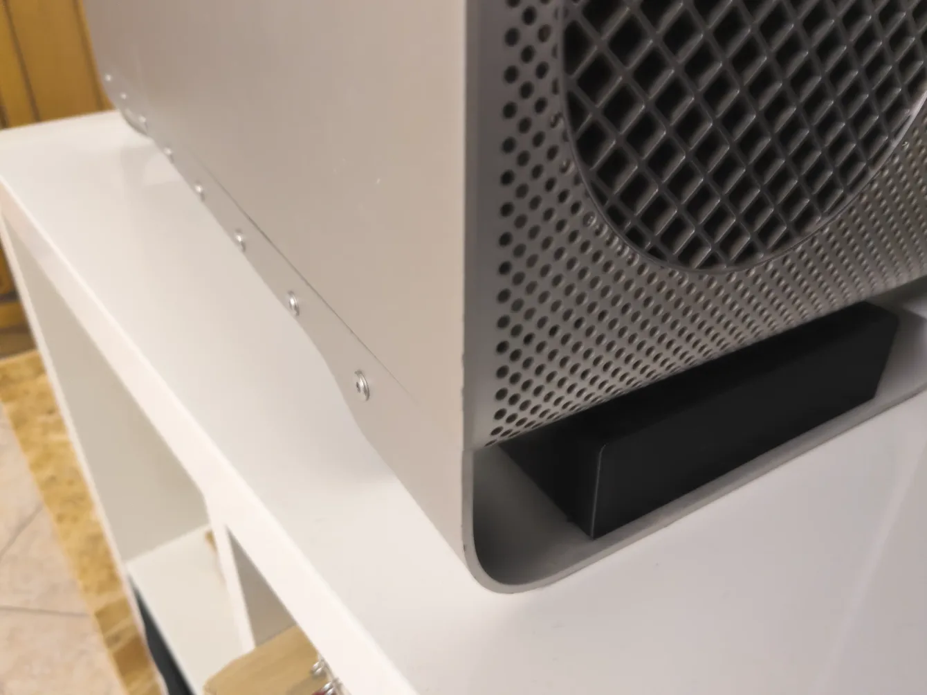
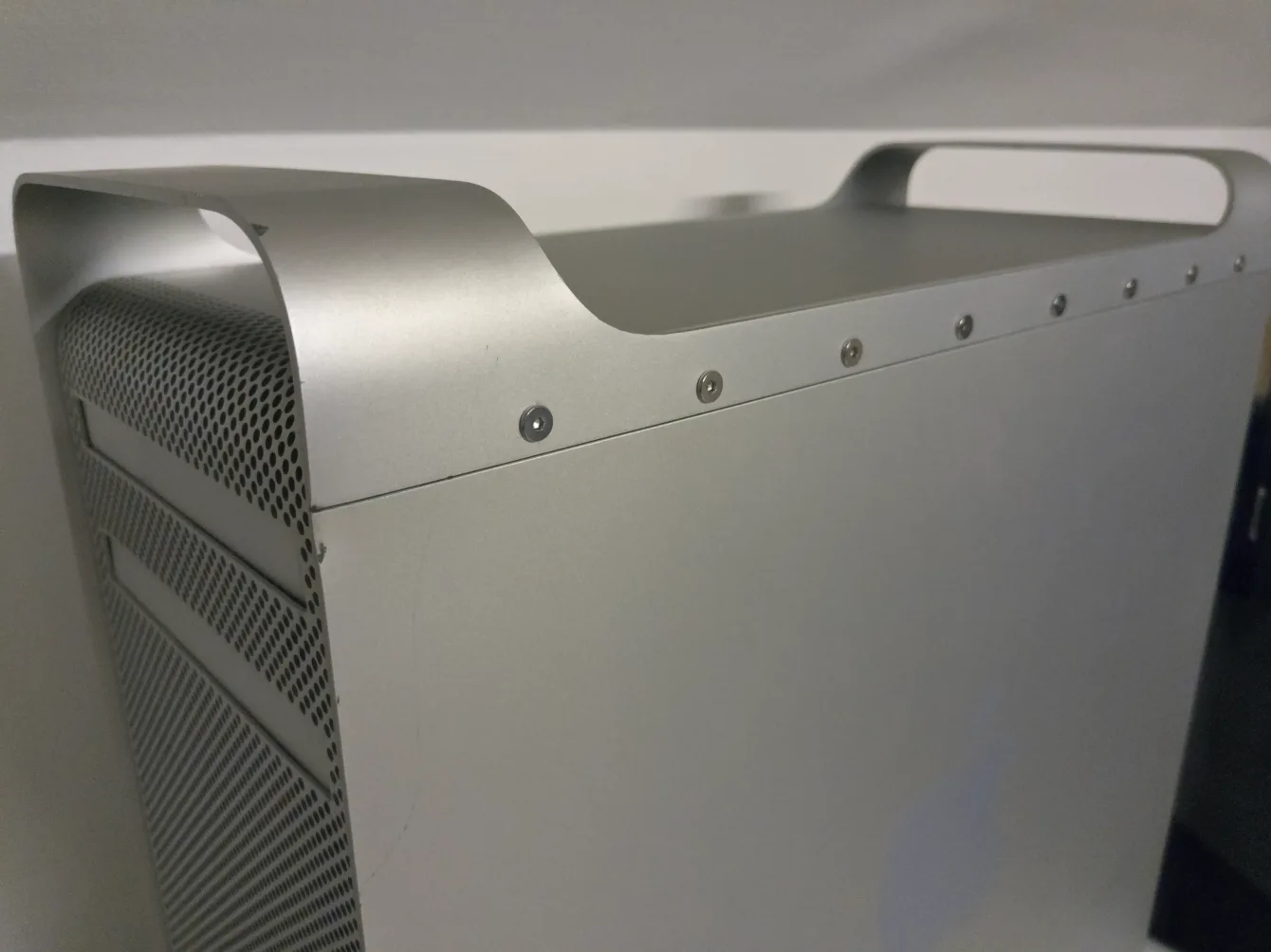
Fixing the bent chassis
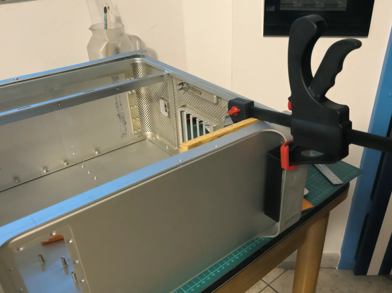
Unfortunately the chassis was broken during shipping.
I “repaired” it by drilling out the broken welded spots, then keeping it aligned with woodworking clamps while using bolts and nuts to keep the panels together. It’s not great to see (now it’s a sort of “Mackenstein” Pro), but at least the case is stable.
03 | Make |
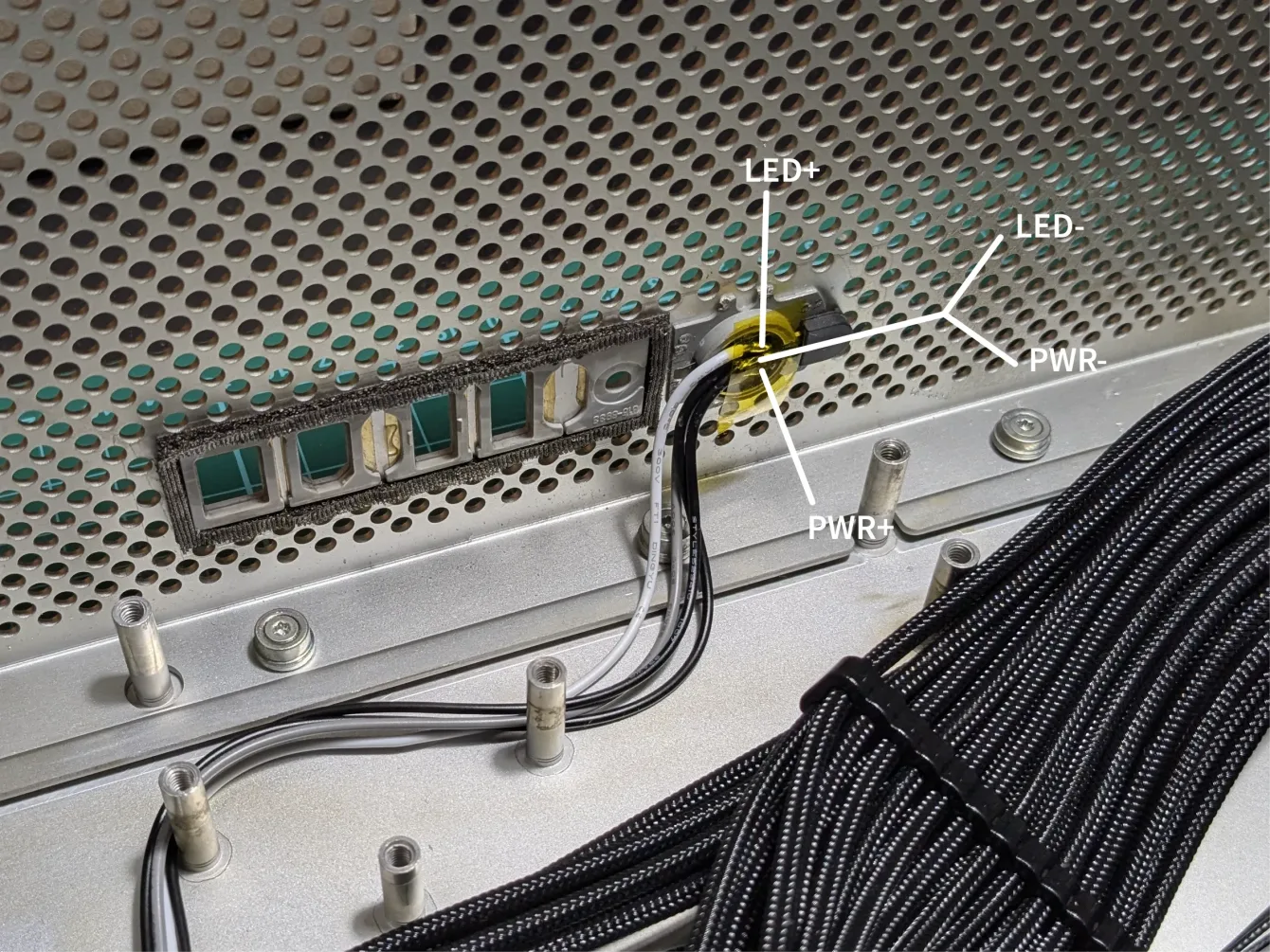
Wiring the front button
The front button PCB has 3 welding pads.
The left is the LED positive, and it goes to the motherboard PWR_LED+ pin
The center is a common ground for both the LED and power button. To work properly it needs to be wired to both PWR_SW- and PWR_LED-. Usually on motherboards is not clearly indicated which side of the PWR_SW is negative; try one side, if it keeps powering on and off, switch side.
The right is the power button positive, and it goes to the motherboard PWR_SW+.
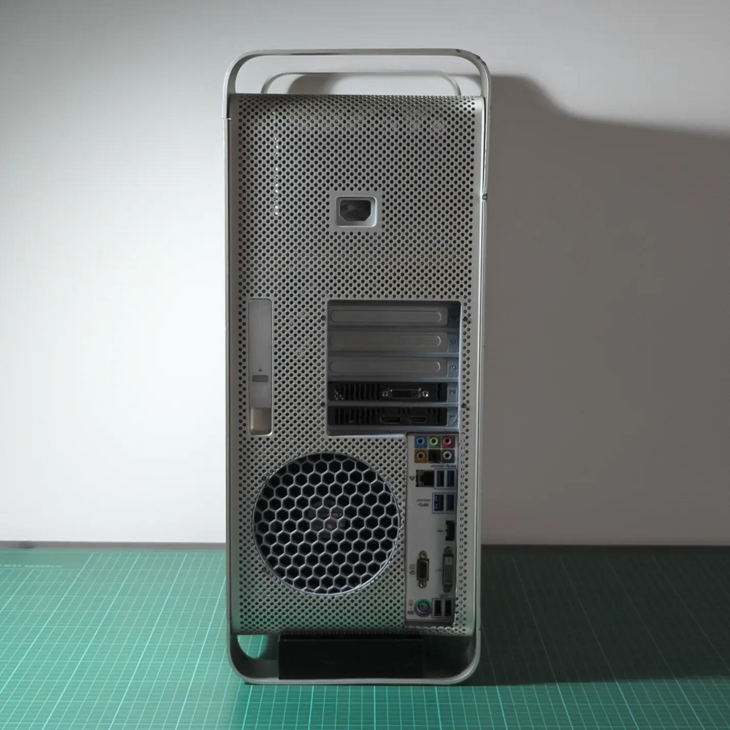
04 | Conclusion
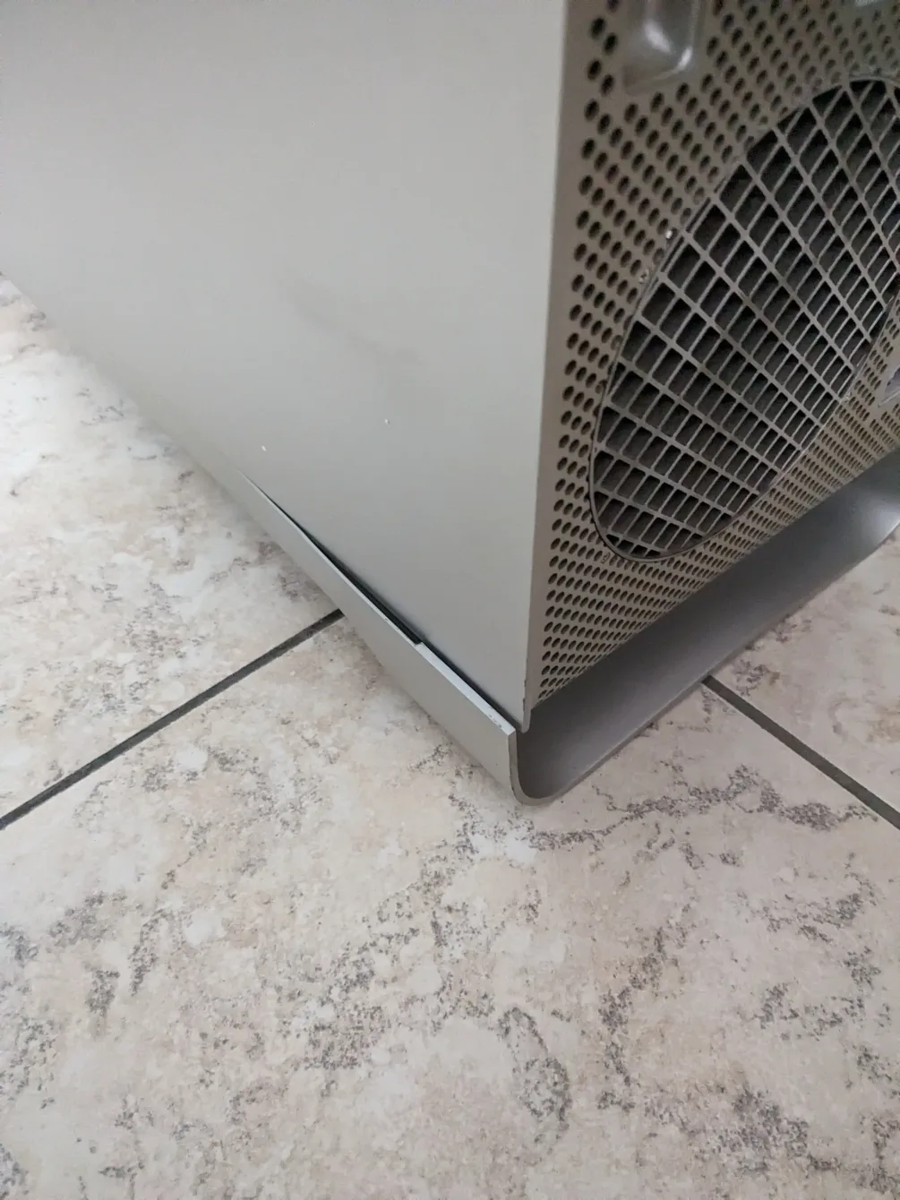
Some photos from the finished product.